Logic Gates :)
What is a logic gate?
- A logic gate is a device that performs a Boolean function (a function where the input(s) and outputs are 1 or 0 / true or false).
- Logic gates are used in electronic circuits and most of them have 2 inputs and 1 output.
- Truth tables are used to show every possible combination of inputs and their corresponding outputs for a logic gate/circuit.
- The logic gates on the OCR A Level Computer Science specification are: AND, OR, NOT & XOR
AND gate
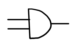


left to right: logic gate diagram, OCR exam notation, javascript notation
- 2 binary inputs, 1 binary output
- Outputs 1 only if both inputs are 1, otherwise outputs 0
OR gate
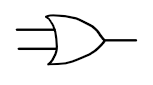


left to right: logic gate diagram, OCR exam notation, javascript notation
- 2 binary inputs, 1 binary output
- Outputs 1 if one or both of the two inputs are 1, otherwise outputs 0
NOT gate
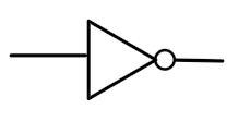

left to right: logic gate diagram, OCR exam notation, javascript notation
- 1 binary input, 1 binary output
- Outputs the opposite value to the input (0 → 1, 1 → 0)
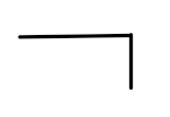
XOR gate
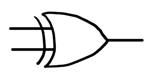

left to right: logic gate diagram, OCR exam notation
- 2 binary inputs, 1 binary output
- XOR is the shorthand for "exclusive OR"
- Outputs 1 only if one of the inputs is 1 and the other is 0, otherwise outputs 0
Beyond the OCR spec:
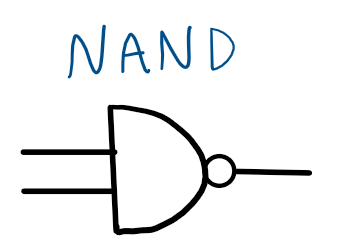

NAND gate:
- 2 binary inputs, 1 binary output
- NAND is shorthand for NOT AND
- Outputs the logical inverse of an AND gate (Outputs 0 only if both inputs are 1, otherwise outputs 1)
NOR gate
- 2 binary inputs, 1 binary output
- NOR is shorthand for NOT OR
- Outputs the logical inverse of an OR gate (Outputs 0 if one or both of the inputs are 1, otherwise outputs 1)
Interactive truth tables!
NOT gate:
Other gates:
- Click buttons to reveal outputs for each logic gate :)
| Input A |
Input B |
Output |
| 0 |
0 |
|
| 0 |
1 |
|
| 1 |
0 |
|
| 1 |
1 |
|